目的
スイッチとルータを使用して、異なるVLAN間(VLAN10とVLAN20)で通信できることを確認する。
接続構成
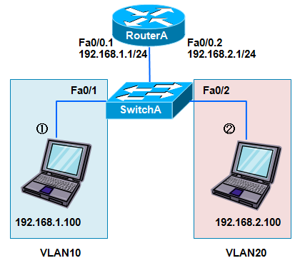
青色の線は、イーサネット接続です。
コンフィグはこちら・・・Config
設定
SwitchA#vlan database
SwitchA(vlan)#vlan 10 name vlan10
VLAN 10 added:
Name: vlan10
SwitchA(vlan)#vlan 20 name vlan20
VLAN 20 added:
Name: vlan20
SwitchA(vlan)#exit
APPLY completed.
Exiting....
SwitchA#conf t
Enter configuration commands, one per line. End with CNTL/Z.
SwitchA(config)#int fa0/1
SwitchA(config-if)#switchport mode access ←アクセスポートに設定
SwitchA(config-if)#switchport access vlan 10 ←VLAN10を割り当てる
SwitchA(config)#int fa0/2
SwitchA(config-if)#switchport mode access ←アクセスポートに設定
SwitchA(config-if)#switchport access vlan 20 ←VLAN20を割り当てる
SwitchA(config-if)#exit
SwitchA(config)#int fa0/24
SwitchA(config-if)#switchport mode trunk ←トランクポートに設定
SwitchA(config-if)#switchport trunk encapsulation dot1q ←トランクプロトコルは802.1Qに設定
SwitchA(config-if)#end
RouterA#conf t
RouterA(config)#int fa0/0.1
RouterA(config-subif)#encapsulation dot1Q 10 トランクプロトコルは802.1Qを使い、VLAN10に所属させる
RouterA(config-subif)#ip add 192.168.1.1 255.255.255.0
RouterA(config)#int fa0/0.2
RouterA(config-subif)#encapsulation dot1Q 20 トランクプロトコルは802.1Qを使い、VLAN20に所属させる
RouterA(config-subif)#ip add 192.168.2.1 255.255.255.0
RouterA(config-subif)#exit
RouterA(config)#int fa0/0
RouterA(config-if)#no shut
RouterA(config-if)#
設定確認
SwitchA#sh vlan ←すべてのVLANに関する情報を表示する。
VLAN Name Status Ports
---- -------------------------------- --------- -------------------------------
1 default active Fa0/3, Fa0/4, Fa0/5, Fa0/6,
Fa0/7, Fa0/8, Fa0/9, Fa0/10,
Fa0/11, Fa0/12, Fa0/13, Fa0/14,
Fa0/15, Fa0/16, Fa0/17, Fa0/18,
Fa0/19, Fa0/20, Fa0/21, Fa0/22,
Fa0/23
10 vlan10 active Fa0/1 ←VLAN10にFa0/1が属している。
また、ステータスが active なのでVLANが有効な状態を示している。
20 vlan20 active Fa0/2 ←VLAN20にFa0/2が属している。
1002 fddi-default active
1003 token-ring-default active
1004 fddinet-default active
1005 trnet-default active
VLAN Type SAID MTU Parent RingNo BridgeNo Stp BrdgMode Trans1 Trans2
---- ----- ---------- ----- ------ ------ -------- ---- -------- ------ ------
1 enet 100001 1500 - - - - - 1002 1003
10 enet 100010 1500 - - - - - 0 0
20 enet 100020 1500 - - - - - 0 0
1002 fddi 101002 1500 - - - - - 1 1003
1003 tr 101003 1500 1005 0 - - srb 1 1002
1004 fdnet 101004 1500 - - 1 ibm - 0 0
1005 trnet 101005 1500 - - 1 ibm - 0 0
SwitchA#
SwitchA#sh int fa0/24 switchport ←スイッチポート(Fa0/10)の設定や状態を表示する。
Name: Fa0/24
Switchport: Enabled ←スイッチポートとして動作している
Administrative mode: trunk ←トランクポートとして設定
Operational Mode: trunk ←トランクポートとして動作
Administrative Trunking Encapsulation: dot1q ←トランクプロトコルは802.1Qとして設定
Operational Trunking Encapsulation: dot1q ←トランクプロトコルは802.1Qとして動作
Negotiation of Trunking: Disabled
Access Mode VLAN: 0 ((Inactive))
Trunking Native Mode VLAN: 1 (default) ←ネイティブVLANは1
Trunking VLANs Enabled: ALL
Trunking VLANs Active: 1,10,20
Pruning VLANs Enabled: 2-1001
Priority for untagged frames: 0
Override vlan tag priority: FALSE
Voice VLAN: none
Appliance trust: none
SwitchA#
RouterA#sh ip int brief
Interface IP-Address OK? Method Status Protocol
FastEthernet0/0 unassigned YES unset up up
FastEthernet0/0.1 192.168.1.1 YES manual up up ←サブインターフェースのステータスがアップ
FastEthernet0/0.2 192.168.2.1 YES manual up up ←サブインターフェースのステータスがアップ
Serial0/0 unassigned YES unset administratively down down
RouterA#
RouterA#sh ip route ←ルーティングテーブルを表示
Codes: C - connected, S - static, I - IGRP, R - RIP, M - mobile, B - BGP
D - EIGRP, EX - EIGRP external, O - OSPF, IA - OSPF inter area
N1 - OSPF NSSA external type 1, N2 - OSPF NSSA external type 2
E1 - OSPF external type 1, E2 - OSPF external type 2, E - EGP
i - IS-IS, su - IS-IS summary, L1 - IS-IS level-1, L2 - IS-IS level-2
ia - IS-IS inter area, * - candidate default, U - per-user static route
o - ODR, P - periodic downloaded static route
Gateway of last resort is not set
C 192.168.1.0/24 is directly connected, FastEthernet0/0.1
C 192.168.2.0/24 is directly connected, FastEthernet0/0.2
VLAN10(192.168.1.0/24)、VLAN20(192.168.2.0/24)を相互に接続し、ルーティング可能な状態であることがわかる。
RouterA#
動作確認
①のPCをSwitchAのFa0/1に接続。 ←VLAN10に所属
②のPCをSwitchBのFa0/2に接続。 ←VLAN20に所属
①のPCからPingコマンドで確認する。
c:\>ping 192.168.2.100
192.168.2.100 に ping を送信しています 32 バイトのデータ:
192.168.2.100 からの応答: バイト数 =32 時間 =1ms TTL=32 ←疎通確認OK。
192.168.2.100 からの応答: バイト数 =32 時間 <1ms TTL=32
192.168.2.100 からの応答: バイト数 =32 時間 <1ms TTL=32
192.168.2.100 からの応答: バイト数 =32 時間 <1ms TTL=32
192.168.2.100 の ping 統計:
パケット数: 送信 = 4、受信 = 4、損失 = 0 (0% の損失)、
ラウンド トリップの概算時間 (ミリ秒):
最小 = 0ms、最大 = 1ms、平均 = 0ms
①のPCをSwitchAのFa0/1に接続。 ←VLAN10に所属
②のPCをSwitchBのFa0/3に接続。 ←VLAN1に所属
①のPCからPingコマンドで確認する。
c:\>ping 192.168.2.100
192.168.2.100 に ping を送信しています 32 バイトのデータ:
要求がタイムアウトしました。 ←疎通確認NG。
要求がタイムアウトしました。
要求がタイムアウトしました。
要求がタイムアウトしました。
192.168.2.100 の ping 統計:
パケット数: 送信 = 4、受信 = 0、損失 = 4 (100% の損失)、
※VLAN1はルーティングさせていないので通信不可となる。