目的
トランク接続にした2台のスイッチで新たにVLANを作成し、作成したVLANにPCを接続する。
お互いのPCが通信できることを確認する。
また、異なるVLANに接続されたPCでは、通信できないことを確認する。
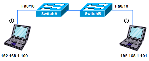
接続構成
設定
SwitchA#vlan database
SwitchA(vlan)#vlan 10 name vlan10
VLAN 10 added:
Name: vlan10
SwitchA(vlan)#exit
APPLY completed.
Exiting....
SwitchA#conf t
Enter configuration commands, one per line. End with CNTL/Z.
SwitchA(config)#int fa0/10
SwitchA(config-if)#switchport mode access ←アクセスポートに設定
SwitchA(config-if)#switchport access vlan 10 ←VLAN10を割り当てる
SwitchA(config-if)#exit
SwitchA(config)#int fa0/24
SwitchB(config-if)#switchport mode trunk ←トランクポートに設定
SwitchA(config-if)#end
SwitchB#vlan database
SwitchB(vlan)#vlan 10 name vlan10
VLAN 10 added:
Name: vlan10
SwitchB(vlan)#exit
APPLY completed.
Exiting....
SwitchB#conf t
Enter configuration commands, one per line. End with CNTL/Z.
SwitchB(config)#int fa0/10
SwitchB(config-if)#switchport mode access ←アクセスポートに設定
SwitchB(config-if)#switchport access vlan 10 ←VLAN10を割り当てる
SwitchB(config-if)#exit
SwitchB(config)#int fa0/24
SwitchB(config-if)#switchport mode trunk ←トランクポートに設定
SwitchB(config-if)#end
設定確認
SwitchA#sh vlan ←すべてのVLANに関する情報を表示する。
VLAN Name Status Ports
---- -------------------------------- --------- -------------------------------
1 default active Fa0/1, Fa0/2, Fa0/3, Fa0/4,
Fa0/5, Fa0/6, Fa0/7, Fa0/8,
Fa0/9, Fa0/11, Fa0/12, Fa0/13,
Fa0/14, Fa0/15, Fa0/16, Fa0/17,
Fa0/18, Fa0/19, Fa0/20, Fa0/21,
Fa0/22, Fa0/23
10 vlan10 active Fa0/10←新たに作成したVLAN10にFa0/10が属している。
また、ステータスが active なのでVLANが有効な状態を示している。
1002 fddi-default active
1003 token-ring-default active
1004 fddinet-default active
1005 trnet-default active
VLAN Type SAID MTU Parent RingNo BridgeNo Stp BrdgMode Trans1 Trans2
---- ----- ---------- ----- ------ ------ -------- ---- -------- ------ ------
1 enet 100001 1500 - - - - - 1002 1003
10 enet 100010 1500 - - - - - 0 0
1002 fddi 101002 1500 - - - - - 1 1003
1003 tr 101003 1500 1005 0 - - srb 1 1002
1004 fdnet 101004 1500 - - 1 ibm - 0 0
1005 trnet 101005 1500 - - 1 ibm - 0 0
SwitchA#
SwitchA#sh int fa0/10 switchport ←スイッチポート(Fa0/10)の設定や状態を表示する。
Name: Fa0/10
Switchport: Enabled ←スイッチポートとして動作している
Administrative mode: static access ←アクセスポートとして設定
Operational Mode: static access ←アクセスポートとして動作
Administrative Trunking Encapsulation: isl
Operational Trunking Encapsulation: isl
Negotiation of Trunking: Disabled
Access Mode VLAN: 10 (vlan10) ←VLAN10が割り当てられている
Trunking Native Mode VLAN: 1 (default)
Trunking VLANs Enabled: NONE
Pruning VLANs Enabled: NONE
Priority for untagged frames: 0
Override vlan tag priority: FALSE
Voice VLAN: none
Appliance trust: none
SwitchA#
SwitchA#sh int fa0/24 switchport
Name: Fa0/24
Switchport: Enabled
Administrative mode: trunk ←トランクポートとして設定
Operational Mode: trunk ←トランクポートとして動作
Administrative Trunking Encapsulation: isl ←トランクプロトコルを isl として設定
Operational Trunking Encapsulation: isl ←トランクプロトコルは isl として動作
Negotiation of Trunking: Disabled
Access Mode VLAN: 0 ((Inactive))
Trunking Native Mode VLAN: 1 (default) ←ネイティブVLANは1になっている。
Trunking VLANs Enabled: ALL
Trunking VLANs Active: 1,10
Pruning VLANs Enabled: 2-1001
Priority for untagged frames: 0
Override vlan tag priority: FALSE
Voice VLAN: none
Appliance trust: none
SwitchA#
動作確認
①のPCをSwitchAのFa0/10に接続。
②のPCをSwitchBのFa0/10に接続。
※同じVLANに接続している。
①のPCからPingコマンドで確認する。
c:\>ping 192.168.1.101
192.168.1.101 に ping を送信しています 32 バイトのデータ:
192.168.1.101 からの応答: バイト数 =32 時間 =1ms TTL=32 ←疎通確認OK。
192.168.1.101 からの応答: バイト数 =32 時間 <1ms TTL=32
192.168.1.101 からの応答: バイト数 =32 時間 <1ms TTL=32
192.168.1.101 からの応答: バイト数 =32 時間 <1ms TTL=32
192.168.1.101 の ping 統計:
パケット数: 送信 = 4、受信 = 4、損失 = 0 (0% の損失)、
ラウンド トリップの概算時間 (ミリ秒):
最小 = 0ms、最大 = 1ms、平均 = 0ms
①のPCをSwitchAのFa0/1に接続。
②のPCをSwitchBのFa0/10に接続。
※異なるVLANに接続している。
①のPCからPingコマンドで確認する。
c:\>ping 192.168.1.101
192.168.1.101 に ping を送信しています 32 バイトのデータ:
要求がタイムアウトしました。 ←疎通確認NG。
要求がタイムアウトしました。
要求がタイムアウトしました。
要求がタイムアウトしました。
192.168.1.101 の ping 統計:
パケット数: 送信 = 4、受信 = 0、損失 = 4 (100% の損失)、